Sensors

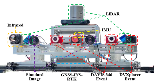
The data collection platform is shown in Fig. 1.. Our sensor suite consists of a multi-camera setup (event camera, industrial camera,
and infrared camera) equipped with three LiDARs, onboard IMU, two GNSS receivers, and GNSS-RTK/INS systems.
The specific specifications of each sensor are presented in Table. 1. .
An Intel NUC (i7-1260P, 32GB RAM) and an industrial computer (i7-10610U, 32GB RAM) are used to run sensor drivers, and record data into ROS bags on the Ubuntu system.
Visual sensors
Two sets of stereo event cameras with different resolutions, DAVIS436 (346×260) and DVXplorer (640×480), are configured at a baseline of 30 cm respectively.
DAVIS346 produces asynchronous events and intensity frames.
In contrast, DVXplorer exclusively generates events, while its resolution surpasses that of DAVIS346, enabling the provision of more intricate scene information.
Each event camera is equipped with additional infrared filters to mitigate interference from LiDAR.
Two FLIR BFLY-U3-23S3C industrial cameras with a resolution of 1920×1200 are used to capture RGB images at 20 Hz in fixed exposure mode.
Forward-facing stereo industrial cameras are installed with a baseline of 30 cm, ensuring fairness by maintaining consistency with the baseline of the stereo event cameras.
Hikrobot MV-CI003-GL-N6 infrared camera collects thermal frames at 20 Hz, encompassing a response band of 8-14μm and equipped with a 6.3mm focal length lens.
Mechanical LiDAR
We configure three mechanical LiDARs including two slanted LiDARs to collect accurate point clouds of surrounding environments.
Velodyne HDL-32E is positioned on the top of the vehicle to capture the surroundings horizontally.
Two slanted LiDARs, Lslidar C16 and Velodyne VLP-16, are mounted on the left and right sides of the sensor kit, respectively.
This configuration facilitates the thorough recording of architectural particulars relevant to high-rising buildings in urbanized
areas and all LiDAR data are collected at 10 Hz.
Onboard IMU and GNSS-RTK/INS suite
An onboard Xsens-MTI-30 IMU is employed to collect the raw acceleration and angular velocity at 400 Hz.
The accurate ground-truth of localization is furnished by a centimeter-level GNSS(GPS, GLONASS, and BeiDou)-RTK/INS(fiber-optic gyroscope) navigation system.
The details of full sensors setup can be found below:
| Sensor Type | Description |
| Inivation DAVIS346 Color × 2 |
|
| Inivation DVXplorer × 2 |
|
| Hikrobot MV-CI003-GL-N6 |
|
| FLIR BFLY-U3-23S3C × 2 |
|
| Velodyne HDL-32E |
|
| Velodyne VLP-16 |
|
| Lslidar C16 |
|
| Xsens Mti-30 IMU |
|
| U-BLOX ZED-F9P |
|
| U-BLOX EVK-M8T |
|
NovAtel SPAN-CPT |
|