Calibration
| Calibration results with rosbag | Event camera | Industrial camera | Infrared camera | LiDAR | IMU |
| Checkboard files | Checkboard files for Event/Industrial cameras | Checkboard files for Infrared camera | The DXF file of infrared checkboard | ||
1. Time synchronization
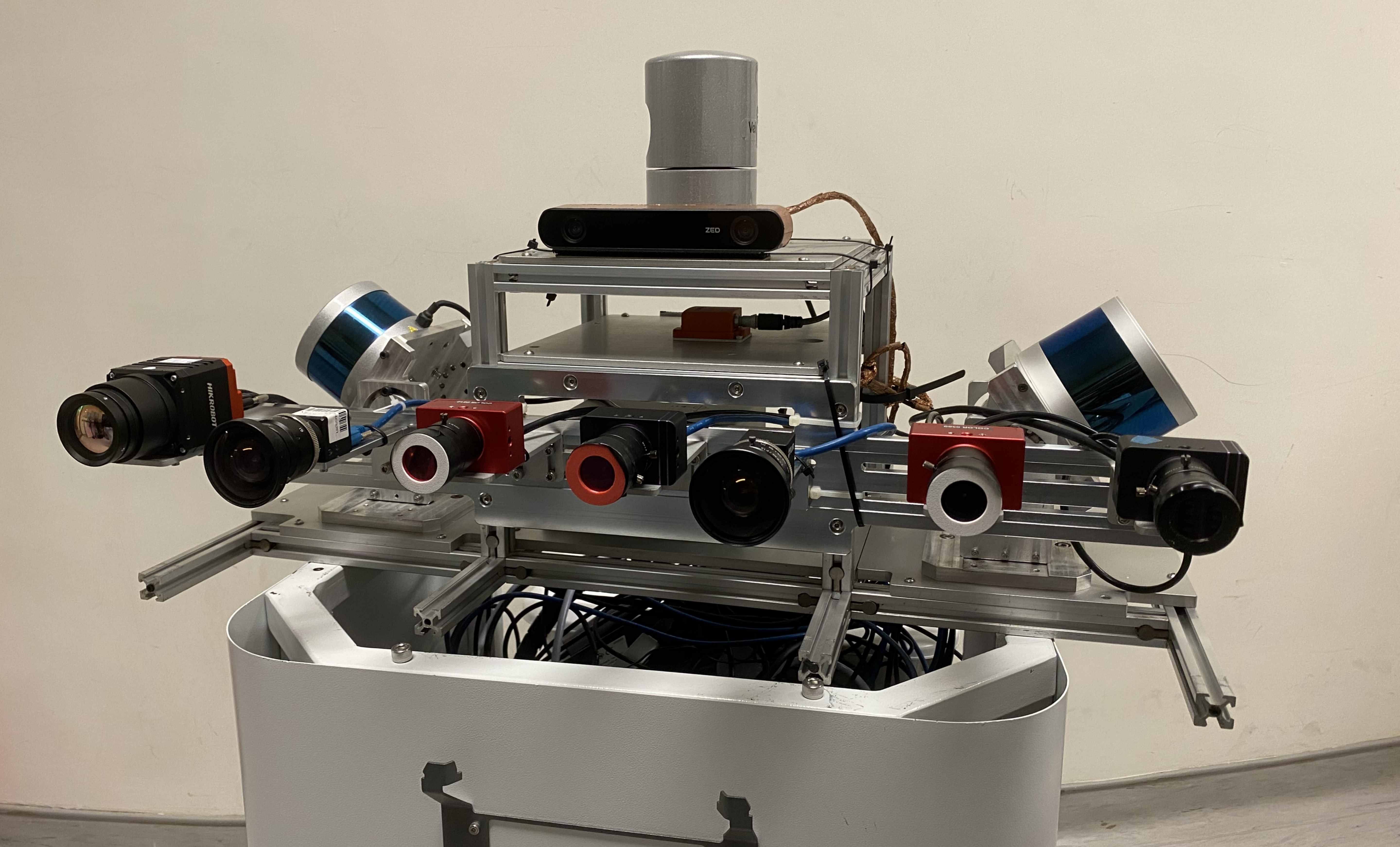
We use a Precision Time Protocol (PTP) device to synchronize the clocks of various data collection devices across the sensor network. The PTP ensures time accuracy within nanoseconds. The synchronization device acquires the NMEA output and pulse-per-second (PPS) signal from a u-blox M8T GNSS receiver to align the ROS time of the onboard computers with the GPS time. This enables sensors such as cameras, LiDAR, and IMU to record timestamps based on the synchronized GPS time.
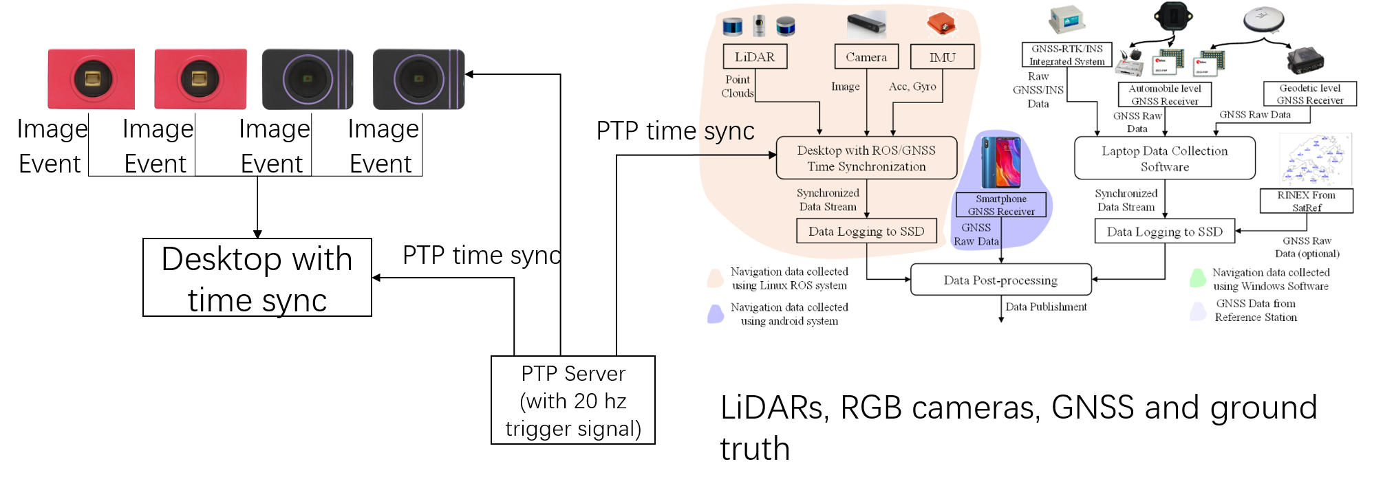
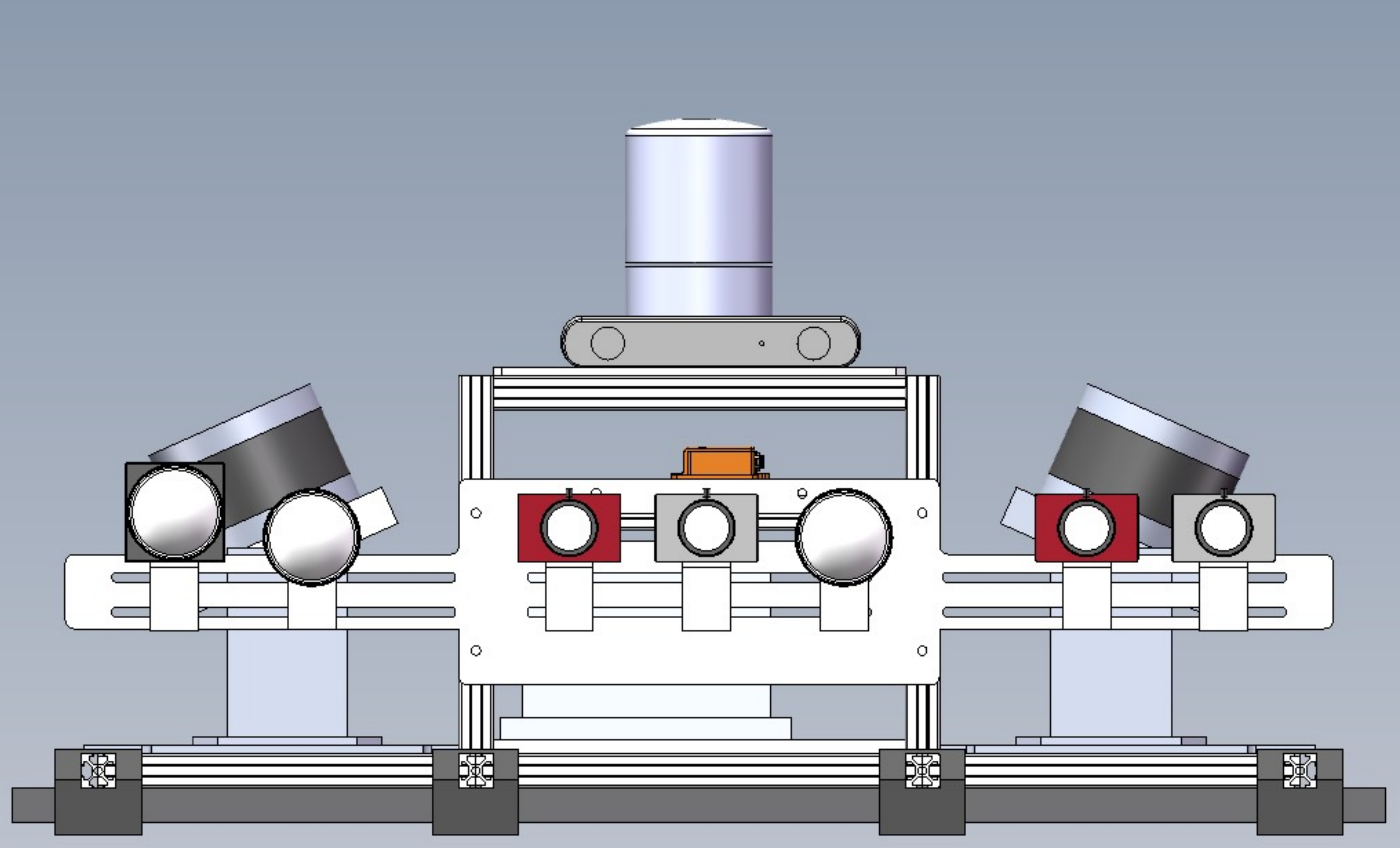
Moreover, to achieve time synchronization between different event cameras, the DAVIS346 on the rightmost side is configured as the master device and transmits trigger signal pulses to the remaining slave event cameras sequentially from left to right via external cables.
The event camera has an additional synchronization interface, called as "sync connectors", as shown in the figure below. (Using DAVIS346 as example reference to Link, same as DVXplorer Link).
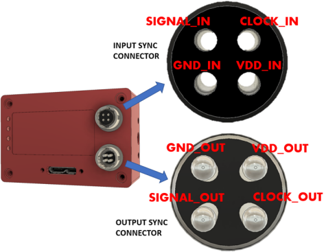
The synchronization connectors are HiRose HR10A-7R-4P (male, SYNC OUTPUT) and HR10A-7R-4S (female, SYNC INPUT) connectors. Cables should use the matching connectors HR10A-7P-4S (female) and HR10A-7P-4P (male). Please note that to keep full electrical isolation between different cameras, the cable should not be shielded, or if it is, the shield should not connect one end of the cable to the other. Input signals can be 3.3V or 5V, depending on the VDD_IN supplied externally, output signals are 5V, as is VDD_OUT. If you chain cameras together for synchronization, the clock and VDD will be 5V, for example.
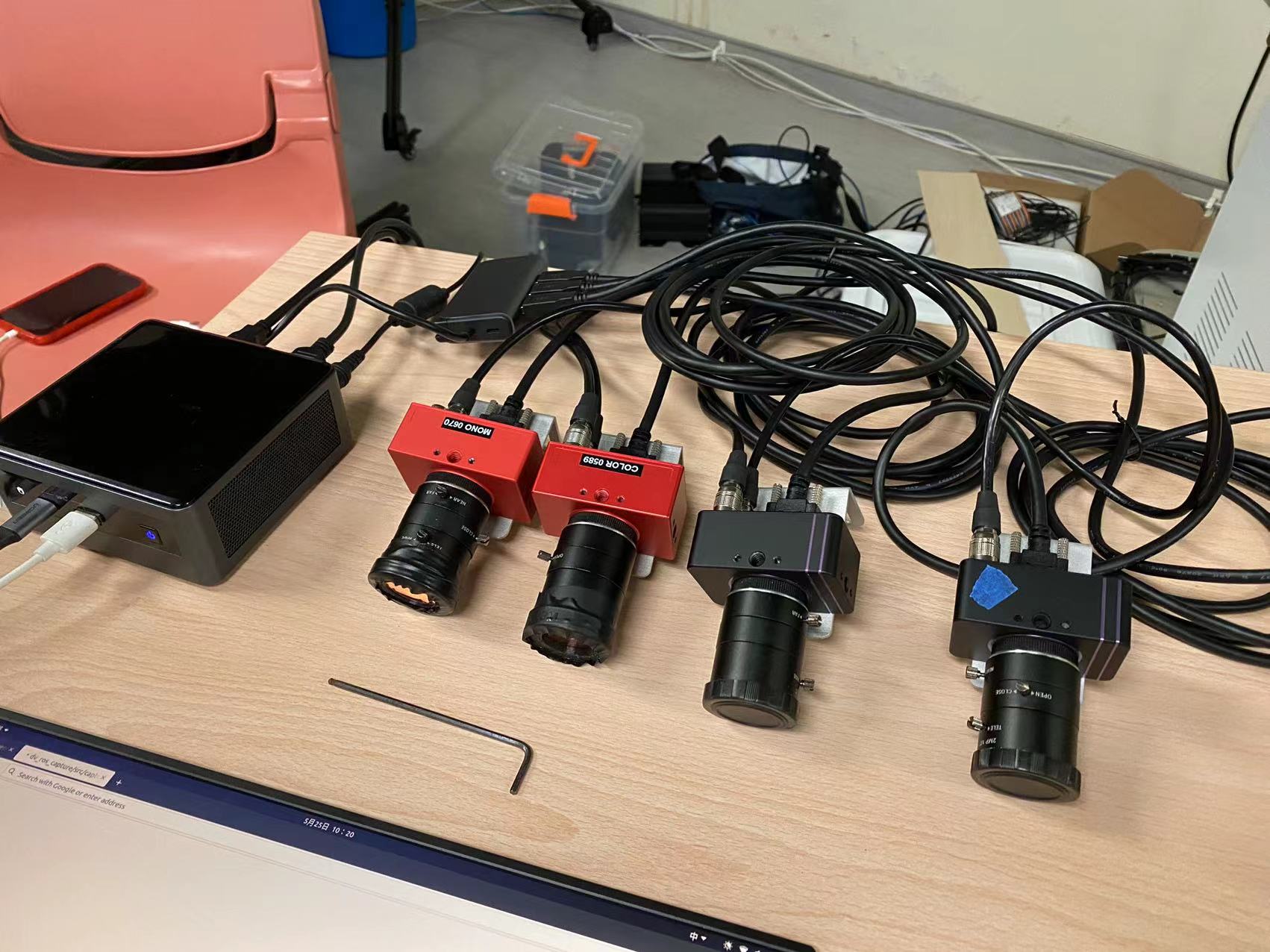
Therefore, utilizing this sync connector, we connected four event cameras together (two DAVIS346 and two DVXplorer) as shown in the diagram below. Additionally, we replaced the event camera ROS driver Code provided by Invitation Company with our own driver Code.
There are two key parameter in the driver code of event camera for synchronization, syncDevices and waitForSync
<rosparam param="syncDevices">["series number of your event camera"]</rosparam>
A list of other cameras connected with synchronization cable to this camera, If this list is empty, the camera node will not properly synchronize them.
<param name="waitForSync" value="true"/>
This means that it does not publish data until synchronization is complete. The launch file of our event camera synchronization can be seen in Link. We use an event camera as "master" while the other three event cameras is waiting on list. Through the series number of the event camera to avoid mis-match.
After synchronizing the clock cycles between two onboard computers, we set the image publishing frequency of DAVIS346 on onboard computer A to 20Hz, and the publishing frequency of the industrial camera on onboard computer B to 20Hz as well. Then, we placed a stopwatch in front of both cameras. We observed the stopwatch values for image topics with the same timestamps from both cameras. After multiple verifications, we concluded that the time difference between the DAVIS346 on onboard computer A and the industrial camera on onboard computer B, directly capturing images, was within 10ms, which aligns with our expectations.
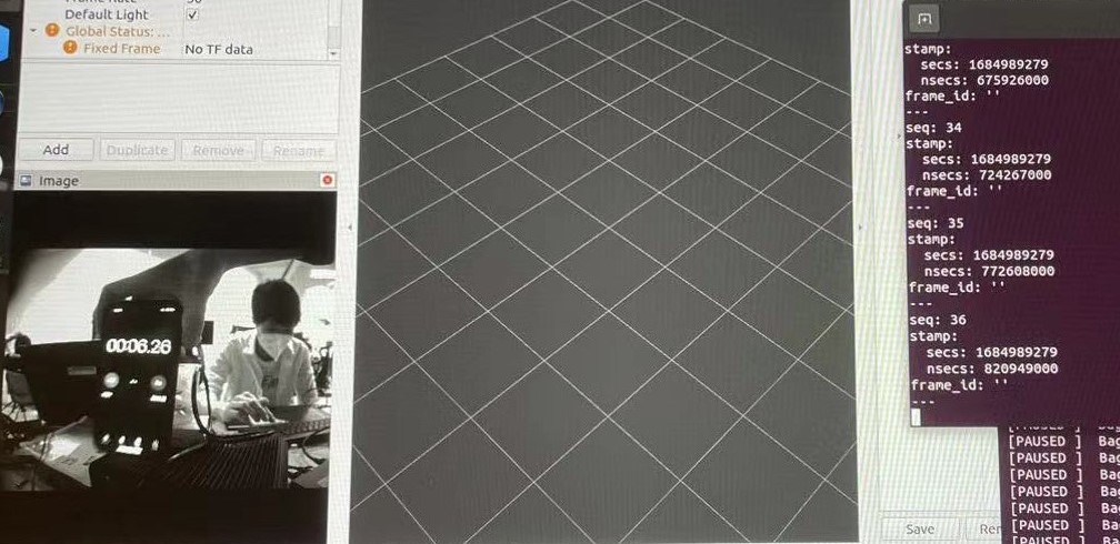
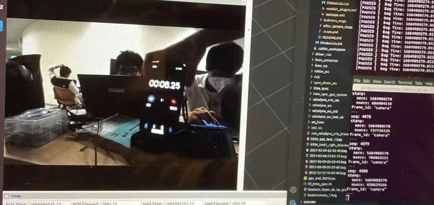
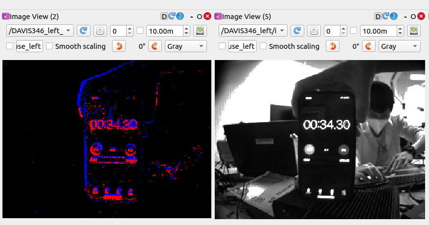
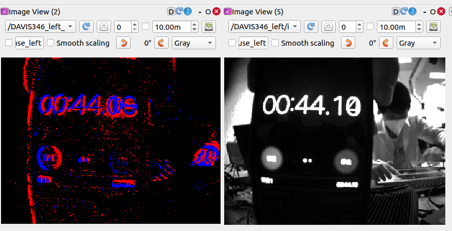
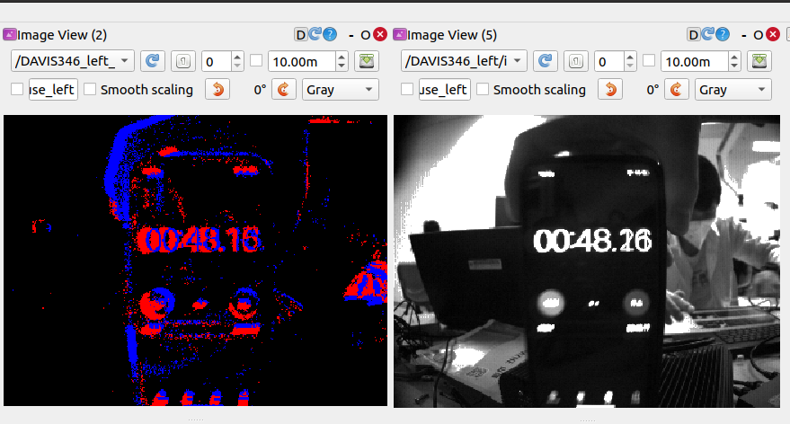
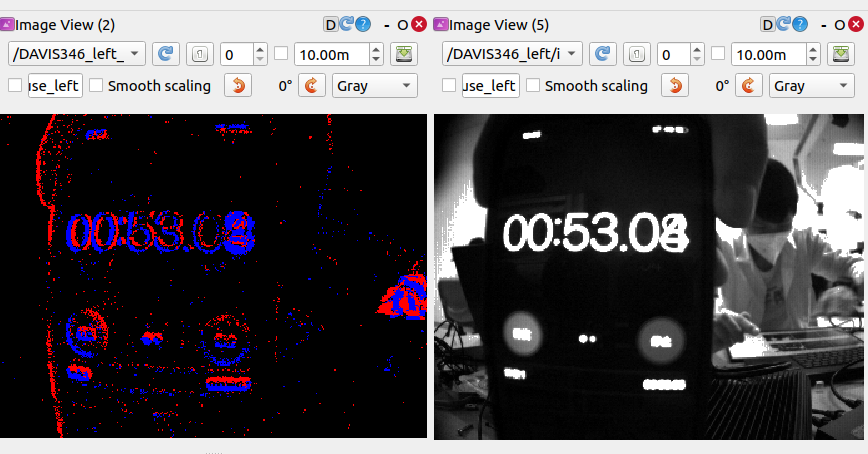
We further test the synchronization between the event and image data streams in DAVIS346 as following:
2. Sensors Calibration
2.1. IMU Calibration
To calibrate the IMU, we position it on a level surface for a duration of three hours, recording the raw measurements. Utilizing the Kalibr toolbox, we can accurately calibrate the random walk and Gaussian white noise of IMU.
2.2. Industrial Cameras Calibration
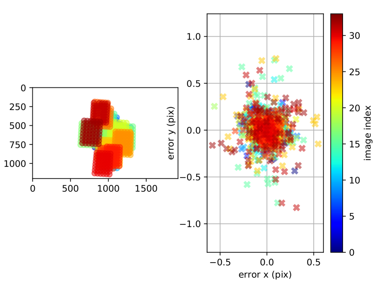
For industrial cameras, we move the sensor platform against the 9×7 checkerboard in the XYZ-axis and collect the sequence of RGB images and IMU. Then intrinsics calibration of industrial cameras is achieved by Kalibr toolbox, where the pinhole and radial-tangential camera models are adopted. The results of intrinsics calibration are shown in Fig. 6..
2.3. Event Cameras Calibration
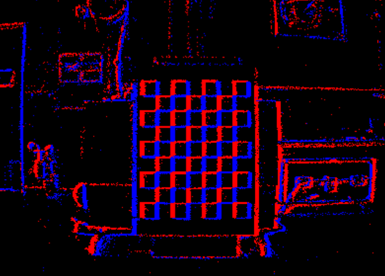
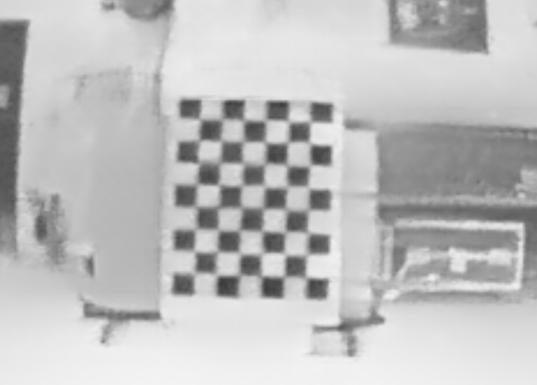
For event cameras, DAVIS346 can produce fixed-rated frames, enabling image-based calibration, while DVXplorer merely produces asynchronous event streams. Therefore, E2Calib is used to achieve image reconstruction from event streams(see Fig. 7.). With the reconstructed checkerboard images in Fig. 8., the intrinsics of event cameras could also be calibrated by Kalibr.
2.4. Calibration of Infrared Cameras
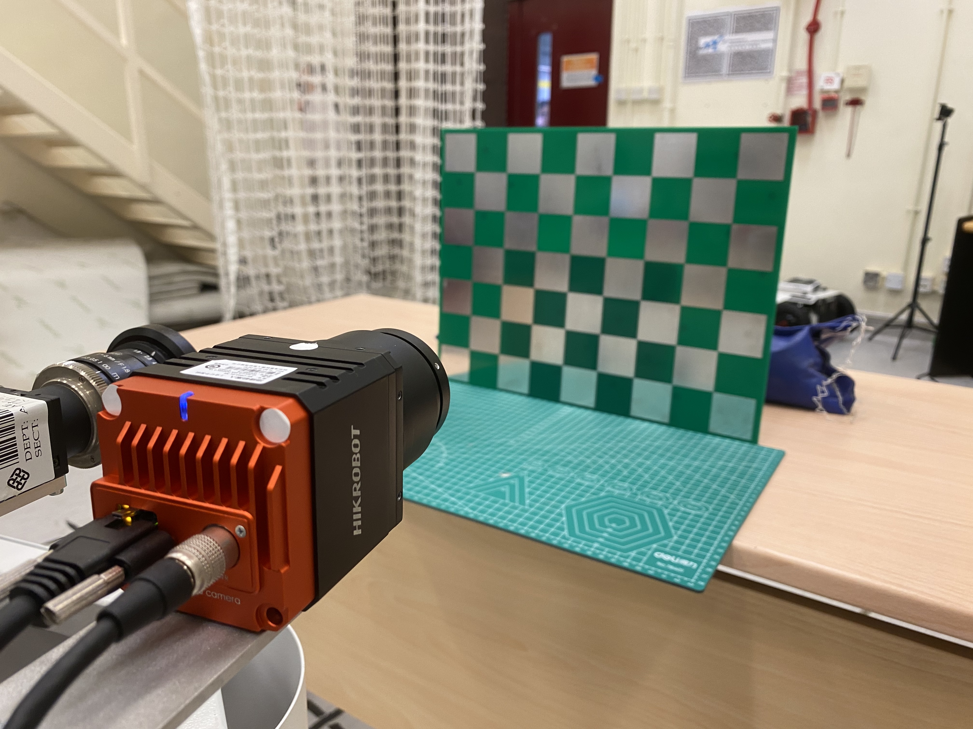
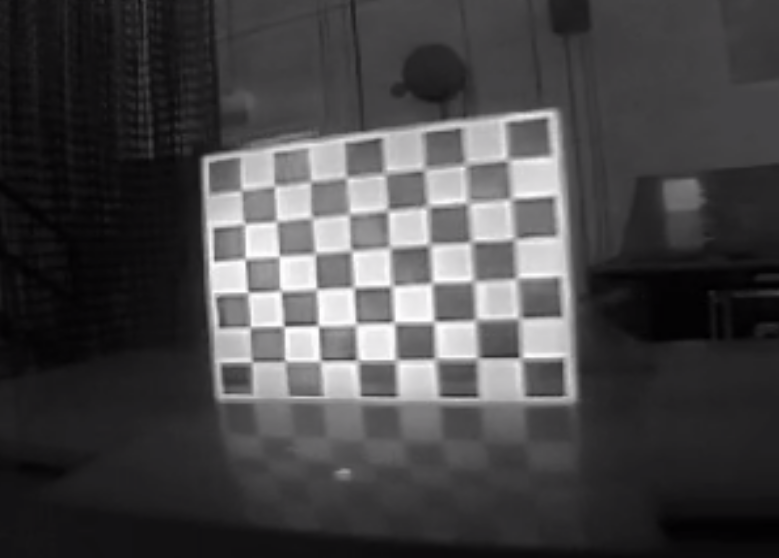
Due to infrared cameras solely capturing the temperature rather than the intensity difference, we design a distinct 9×7 checkerboard to make the pattern detectable for infrared cameras. As shown in Fig. 9., the checkerboard intervals are affixed with aluminum materials, and then using a heating plate to raise the temperature of the checkerboard. Since the superior thermal dissipation of aluminum compared to plastic, a temperature contrast emerges between the two materials, enabling infrared cameras to distinctly capture the lattice shape of the checkerboard, as in Fig. 10.. With the special infrared image of the checkerboard, intrinsic can be calibrated by Kalibr.
2.5. Calibration between Camera and IMU
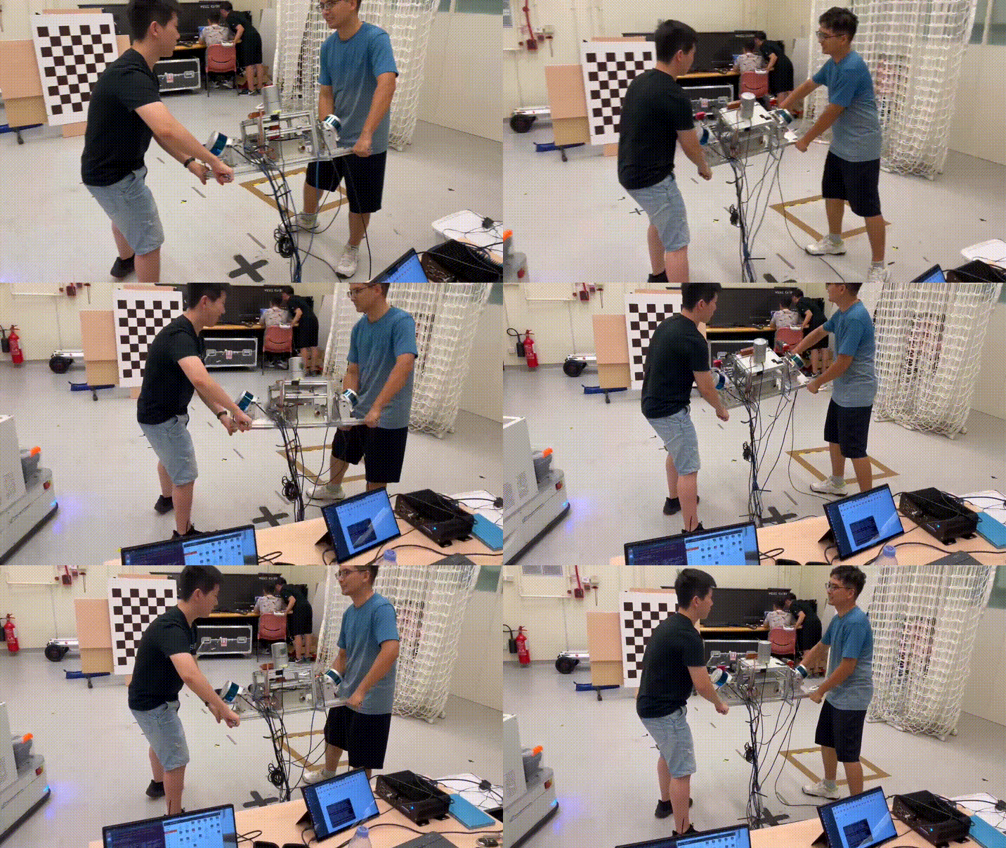
After completing intrinsic calibration, we move the sensor suite in front of checkerboards along the XYZ-RPY-axis and collect data simultaneously. Subsequently, the extrinsic and the temporal offset between all cameras and IMU could be estimated using Kalibr.

2.6. Calibration between LiDAR and IMU
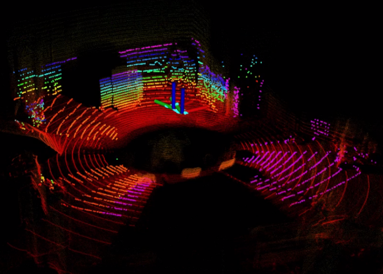
For the calibration of mechanical LiDAR, LI-Init is capable of achieving temporal and spatial calibration for LiDAR and IMU without checkerboards or extra devices in Fig. 12.. We rotate and move the device around the XYZ-axis to ensure sufficient excitation until the data accumulation is completed, thus we acquire the extrinsic transformation between LiDAR and IMU.
